Just to get this out of the way right off the bat, I could have purchased HartK’s PCB and come in 12 weeks and $100 underbudget, but that wasn’t what this project is about.
With a Voron V2.4 R2 build in the works (i.e.: parts on order), I wanted to use this opportunity to finally tackle the task of creating my own PCB and putting it to use. Being that the tool head PCB is essentially just a breakout board with no logic happening, it seemed like the perfect entry into PCB design.
CANBus seems to be popping up more and more and while it’s probably the logical choice, I decided to try and cram all these wires in some drag chains and struggle my way through it like everyone before me. We can do CANBus down the road.
One of my goals was to create the PCB from scratch. Now, I know that HartK already created this, but I didn’t want to start with his Gerber files, CAD designs or follow any of his traces. First, I started with opening the Stealthburner CAD model and creating a rough footprint of the room I would have to work with. After that, I could begin the initial PCB layout design. Being that I have a rough understanding of Fusion 360, I decided to try to utilize the built in PCB tools to tackle this. After the first evening I was thoroughly frustrated and discouraged. Despite the amount of tutorials and videos I watched, nothing was clicking and I kept getting errors about how the 2D model didn’t match the 3D model which had issues with the schematic. After some more research I decided to download KiCad and give that a try. Don’t get me wrong, there were still some steep learning curves that I was dealing with while learning the nuances of PCB design, but it was far more intuitive that Eagle or Fusion’s built in tools.
I wanted to make my design different from HartK’s, but once again was quickly growing frustrated with the limited amount of room I had to work with. To no surprise, I ended up with a design that looked very similar. I went through many revisions early on, where one small change would require almost all PCB traces to be removed and redone. There’s a level of planning and looking forward to the PCB design that I was previously blind to, and this is such a simple board at that.
I turned to r/PrintedCircuitBoard once I felt pretty good about my design and they quickly gave me a load of advice on revisions to make. Back to the drawing board. At this point though I was starting to feel pretty good about what I had going on. I understood that HartK’s board was intended to work with multiple printers but I was just focused on functionality for my single machine. With that, I wanted to reintroduce a dedicated Chamber Temp sensor along with three status LEDs for the part fan, hot end fan and hot end heater. The three LEDs are tied to a solder joint so if there turns out to be any issues, I can remove them from the circuit without having to scrap the entire board (or cut through traces).
One of the last revisions I made was to space the PCB out far enough from the tool head that I could close the center of the board and regain a fair amount of real estate. Doing this required a rework of the tool head Main Body and Cable Cover for the PCB. I added roughly 5mm to the right side of the Main Body and Cable Cover to accomplish this but was pretty satisfied with the aesthetics of it in the end.
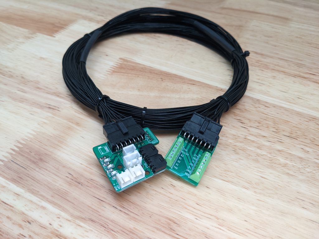
The last piece to the project that I decided to add was a breakout board for down in the electrical bay. It will have the same 14-pin Molex connector as the tool head PCB and allow for a simple 14 wire harness between the two. The breakout board will then have two 7-pin screw terminals to make connections for the jumpers going to the MCU, power supplies and RPi.
I used JLCPCB to order both boards. For $14 shipped, I got 5 of each board on the way. Hard to wrap my head around that.
Current Status: Work in Progress
- Silkscreen labeling needs updated at LEDs
- HE0 connector doesn't fit do to cover mount location
- Extruder plug moved to front of board
- Breakout board needs ground fill and mounting holes
3MF and Gerber Files
3MF and Gerber files are available for download on my GitHub page below.
https://github.com/DeW-Z/Stealthburner-Toolhead-PCB-ModCAD Views with Modified Body and PCB
PCB Design


It’s actually a cool and helpful piece of info.
I am happy that you simply shared this useful information with us.
Please stay us up to date like this. Thanks for sharing.